The moment of inertia, otherwise known as the mass moment of inertia, angular/rotational mass, second moment of mass, or most accurately, rotational inertia, of a rigid body is a quantity that determines the torque needed for a desired angular acceleration about a rotational axis, akin to how mass determines the force needed for a desired acceleration. It depends on the body's mass distribution and the axis chosen, with larger moments requiring more torque to change the body's rate of rotation by a given amount.
Moment of inertia
Flywheels have large moments of inertia to smooth out changes in rates of rotational motion.
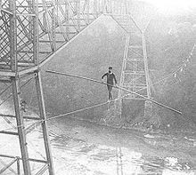
Tightrope walkers use the moment of inertia of a long rod for balance as they walk the rope. Samuel Dixon crossing the Niagara River in 1890.
To improve their maneuverability, combat aircraft are designed to minimize moments of inertia, while civil aircraft often are not.
It is an extensive (additive) property: for a point mass the moment of inertia is simply the mass times the square of the perpendicular distance to the axis of rotation. The moment of inertia of a rigid composite system is the sum of the moments of inertia of its component subsystems (all taken about the same axis). Its simplest definition is the second moment of mass with respect to distance from an axis.
For bodies constrained to rotate in a plane, only their moment of inertia about an axis perpendicular to the plane, a scalar value, matters. For bodies free to rotate in three dimensions, their moments can be described by a symmetric 3-by-3 matrix, with a set of mutually perpendicular principal axes for which this matrix is diagonal and torques around the axes act independently of each other.
When a body is free to rotate around an axis, torque must be applied to change its angular momentum. The amount of torque needed to cause any given angular acceleration (the rate of change in angular velocity) is proportional to the moment of inertia of the body. Moments of inertia may be expressed in units of kilogram metre squared (kg·m2) in SI units and pound-foot-second squared (lbf·ft·s2) in imperial or US units.
The moment of inertia plays the role in rotational kinetics that mass (inertia) plays in linear kinetics—both characterize the resistance of a body to changes in its motion. The moment of inertia depends on how mass is distributed around an axis of rotation, and will vary depending on the chosen axis. For a point-like mass, the moment of inertia about some axis is given by , where is the distance of the point from the axis, and is the mass. For an extended rigid body, the moment of inertia is just the sum of all the small pieces of mass multiplied by the square of their distances from the axis in rotation. For an extended body of a regular shape and uniform density, this summation sometimes produces a simple expression that depends on the dimensions, shape and total mass of the object.
In 1673, Christiaan Huygens introduced this parameter in his study of the oscillation of a body hanging from a pivot, known as a compound pendulum.[2] The term moment of inertia ("momentum inertiae" in Latin) was introduced by Leonhard Euler in his book Theoria motus corporum solidorum seu rigidorum in 1765,[2][3] and it is incorporated into Euler's second law.
The natural frequency of oscillation of a compound pendulum is obtained from the ratio of the torque imposed by gravity on the mass of the pendulum to the resistance to acceleration defined by the moment of inertia. Comparison of this natural frequency to that of a simple pendulum consisting of a single point of mass provides a mathematical formulation for moment of inertia of an extended body.[4][5]
The moment of inertia also appears in momentum, kinetic energy, and in Newton's laws of motion for a rigid body as a physical parameter that combines its shape and mass. There is an interesting difference in the way moment of inertia appears in planar and spatial movement. Planar movement has a single scalar that defines the moment of inertia, while for spatial movement the same calculations yield a 3 × 3 matrix of moments of inertia, called the inertia matrix or inertia tensor.[6][7]
The moment of inertia of a rotating flywheel is used in a machine to resist variations in applied torque to smooth its rotational output. The moment of inertia of an airplane about its longitudinal, horizontal and vertical axes determine how steering forces on the control surfaces of its wings, elevators and rudder(s) affect the plane's motions in roll, pitch and yaw.
Definitionedit
The moment of inertia is defined as the product of mass of section and the square of the distance between the reference axis and the centroid of the section.
Spinning figure skaters can reduce their moment of inertia by pulling in their arms, allowing them to spin faster due to conservation of angular momentum.Video of rotating chair experiment, illustrating moment of inertia. When the spinning professor pulls his arms, his moment of inertia decreases; to conserve angular momentum, his angular velocity increases.
The moment of inertia I is also defined as the ratio of the net angular momentumL of a system to its angular velocityω around a principal axis,[8][9] that is
If the angular momentum of a system is constant, then as the moment of inertia gets smaller, the angular velocity must increase. This occurs when spinning figure skaters pull in their outstretched arms or divers curl their bodies into a tuck position during a dive, to spin faster.[8][9][10][11][12][13][14]
For a simple pendulum, this definition yields a formula for the moment of inertia I in terms of the mass m of the pendulum and its distance r from the pivot point as,
Thus, the moment of inertia of the pendulum depends on both the mass m of a body and its geometry, or shape, as defined by the distance r to the axis of rotation.
This simple formula generalizes to define moment of inertia for an arbitrarily shaped body as the sum of all the elemental point masses dm each multiplied by the square of its perpendicular distance r to an axis k. An arbitrary object's moment of inertia thus depends on the spatial distribution of its mass.
In general, given an object of mass m, an effective radius k can be defined, dependent on a particular axis of rotation, with such a value that its moment of inertia around the axis is
Mathematically, the moment of inertia of a simple pendulum is the ratio of the torque due to gravity about the pivot of a pendulum to its angular acceleration about that pivot point. For a simple pendulum this is found to be the product of the mass of the particle with the square of its distance to the pivot, that is
This can be shown as follows: The force of gravity on the mass of a simple pendulum generates a torque around the axis perpendicular to the plane of the pendulum movement. Here is the distance vector from the torque axis to the pendulum center of mass, and is the net force on the mass. Associated with this torque is an angular acceleration, , of the string and mass around this axis. Since the mass is constrained to a circle the tangential acceleration of the mass is . Since the torque equation becomes:
where is a unit vector perpendicular to the plane of the pendulum. (The second to last step uses the vector triple product expansion with the perpendicularity of and .) The quantity is the moment of inertia of this single mass around the pivot point.
The quantity also appears in the angular momentum of a simple pendulum, which is calculated from the velocity of the pendulum mass around the pivot, where is the angular velocity of the mass about the pivot point. This angular momentum is given by
using a similar derivation to the previous equation.
Similarly, the kinetic energy of the pendulum mass is defined by the velocity of the pendulum around the pivot to yield
This shows that the quantity is how mass combines with the shape of a body to define rotational inertia. The moment of inertia of an arbitrarily shaped body is the sum of the values for all of the elements of mass in the body.
Compound pendulumsedit
Pendulums used in Mendenhall gravimeter apparatus, from 1897 scientific journal. The portable gravimeter developed in 1890 by Thomas C. Mendenhall provided the most accurate relative measurements of the local gravitational field of the Earth.
A compound pendulum is a body formed from an assembly of particles of continuous shape that rotates rigidly around a pivot. Its moment of inertia is the sum of the moments of inertia of each of the particles that it is composed of.[15][16]: 395–396 [17]: 51–53 The naturalfrequency () of a compound pendulum depends on its moment of inertia, ,
where is the mass of the object, is local acceleration of gravity, and is the distance from the pivot point to the center of mass of the object. Measuring this frequency of oscillation over small angular displacements provides an effective way of measuring moment of inertia of a body.[18]: 516–517
Thus, to determine the moment of inertia of the body, simply suspend it from a convenient pivot point so that it swings freely in a plane perpendicular to the direction of the desired moment of inertia, then measure its natural frequency or period of oscillation (), to obtain
where is the period (duration) of oscillation (usually averaged over multiple periods).
Center of oscillationedit
A simple pendulum that has the same natural frequency as a compound pendulum defines the length from the pivot to a point called the center of oscillation of the compound pendulum. This point also corresponds to the center of percussion. The length is determined from the formula,
or
The seconds pendulum, which provides the "tick" and "tock" of a grandfather clock, takes one second to swing from side-to-side. This is a period of two seconds, or a natural frequency of for the pendulum. In this case, the distance to the center of oscillation, , can be computed to be
Notice that the distance to the center of oscillation of the seconds pendulum must be adjusted to accommodate different values for the local acceleration of gravity. Kater's pendulum is a compound pendulum that uses this property to measure the local acceleration of gravity, and is called a gravimeter.
Measuring moment of inertiaedit
The moment of inertia of a complex system such as a vehicle or airplane around its vertical axis can be measured by suspending the system from three points to form a trifilar pendulum. A trifilar pendulum is a platform supported by three wires designed to oscillate in torsion around its vertical centroidal axis.[19] The period of oscillation of the trifilar pendulum yields the moment of inertia of the system.[20]
Moment of inertia of areaedit
Moment of inertia of area is also known as the second moment of area.
These calculations are commonly used in civil engineering for structural design of beams and columns. Cross-sectional areas calculated for vertical moment of the x-axis and horizontal moment of the y-axis .
Height (h) and breadth (b) are the linear measures, except for circles, which are effectively half-breadth derived,
Four objects with identical masses and radii racing down a plane while rolling without slipping. From back to front:
spherical shell,
solid sphere,
cylindrical ring, and
solid cylinder.
The time for each object to reach the finishing line depends on their moment of inertia. (OGV version)
The moment of inertia about an axis of a body is calculated by summing for every particle in the body, where is the perpendicular distance to the specified axis. To see how moment of inertia arises in the study of the movement of an extended body, it is convenient to consider a rigid assembly of point masses. (This equation can be used for axes that are not principal axes provided that it is understood that this does not fully describe the moment of inertia.[22])
Consider the kinetic energy of an assembly of masses that lie at the distances from the pivot point , which is the nearest point on the axis of rotation. It is the sum of the kinetic energy of the individual masses,[18]: 516–517 [23]: 1084–1085 [23]: 1296–1300
This shows that the moment of inertia of the body is the sum of each of the terms, that is
Thus, moment of inertia is a physical property that combines the mass and distribution of the particles around the rotation axis. Notice that rotation about different axes of the same body yield different moments of inertia.
The moment of inertia of a continuous body rotating about a specified axis is calculated in the same way, except with infinitely many point particles. Thus the limits of summation are removed, and the sum is written as follows:
Another expression replaces the summation with an integral,
Here, the function gives the mass density at each point , is a vector perpendicular to the axis of rotation and extending from a point on the rotation axis to a point in the solid, and the integration is evaluated over the volume of the body . The moment of inertia of a flat surface is similar with the mass density being replaced by its areal mass density with the integral evaluated over its area.
Note on second moment of area: The moment of inertia of a body moving in a plane and the second moment of area of a beam's cross-section are often confused. The moment of inertia of a body with the shape of the cross-section is the second moment of this area about the -axis perpendicular to the cross-section, weighted by its density. This is also called the polar moment of the area, and is the sum of the second moments about the - and -axes.[24] The stresses in a beam are calculated using the second moment of the cross-sectional area around either the -axis or -axis depending on the load.
Examplesedit
The moment of inertia of a compound pendulum constructed from a thin disc mounted at the end of a thin rod that oscillates around a pivot at the other end of the rod, begins with the calculation of the moment of inertia of the thin rod and thin disc about their respective centers of mass.[23]
The moment of inertia of a thin rod with constant cross-section and density and with length about a perpendicular axis through its center of mass is determined by integration.[23]: 1301 Align the -axis with the rod and locate the origin its center of mass at the center of the rod, then
where is the mass of the rod.
The moment of inertia of a thin disc of constant thickness , radius , and density about an axis through its center and perpendicular to its face (parallel to its axis of rotational symmetry) is determined by integration.[23]: 1301 [failed verification] Align the -axis with the axis of the disc and define a volume element as , then
where is its mass.
The moment of inertia of the compound pendulum is now obtained by adding the moment of inertia of the rod and the disc around the pivot point as,
where is the length of the pendulum. Notice that the parallel axis theorem is used to shift the moment of inertia from the center of mass to the pivot point of the pendulum.
A list of moments of inertia formulas for standard body shapes provides a way to obtain the moment of inertia of a complex body as an assembly of simpler shaped bodies. The parallel axis theorem is used to shift the reference point of the individual bodies to the reference point of the assembly.
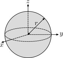
As one more example, consider the moment of inertia of a solid sphere of constant density about an axis through its center of mass. This is determined by summing the moments of inertia of the thin discs that can form the sphere whose centers are along the axis chosen for consideration. If the surface of the ball is defined by the equation[23]: 1301
then the square of the radius of the disc at the cross-section along the -axis is
Therefore, the moment of inertia of the ball is the sum of the moments of inertia of the discs along the -axis,
where is the mass of the sphere.
Rigid bodyedit
The cylinders with higher moment of inertia roll down a slope with a smaller acceleration, as more of their potential energy needs to be converted into the rotational kinetic energy.
If a mechanical system is constrained to move parallel to a fixed plane, then the rotation of a body in the system occurs around an axis parallel to this plane. In this case, the moment of inertia of the mass in this system is a scalar known as the polar moment of inertia. The definition of the polar moment of inertia can be obtained by considering momentum, kinetic energy and Newton's laws for the planar movement of a rigid system of particles.[15][18][25][26]
If a system of particles, , are assembled into a rigid body, then the momentum of the system can be written in terms of positions relative to a reference point , and absolute velocities :
where is the angular velocity of the system and is the velocity of .
For planar movement the angular velocity vector is directed along the unit vector which is perpendicular to the plane of movement. Introduce the unit vectors from the reference point to a point , and the unit vector , so
This defines the relative position vector and the velocity vector for the rigid system of the particles moving in a plane.
Note on the cross product: When a body moves parallel to a ground plane, the trajectories of all the points in the body lie in planes parallel to this ground plane. This means that any rotation that the body undergoes must be around an axis perpendicular to this plane. Planar movement is often presented as projected onto this ground plane so that the axis of rotation appears as a point. In this case, the angular velocity and angular acceleration of the body are scalars and the fact that they are vectors along the rotation axis is ignored. This is usually preferred for introductions to the topic. But in the case of moment of inertia, the combination of mass and geometry benefits from the geometric properties of the cross product. For this reason, in this section on planar movement the angular velocity and accelerations of the body are vectors perpendicular to the ground plane, and the cross product operations are the same as used for the study of spatial rigid body movement.
Angular momentumedit
The angular momentum vector for the planar movement of a rigid system of particles is given by[15][18]
and define the moment of inertia relative to the center of mass as
then the equation for angular momentum simplifies to[23]: 1028
The moment of inertia about an axis perpendicular to the movement of the rigid system and through the center of mass is known as the polar moment of inertia. Specifically, it is the second moment of mass with respect to the orthogonal distance from an axis (or pole).
For a given amount of angular momentum, a decrease in the moment of inertia results in an increase in the angular velocity. Figure skaters can change their moment of inertia by pulling in their arms. Thus, the angular velocity achieved by a skater with outstretched arms results in a greater angular velocity when the arms are pulled in, because of the reduced moment of inertia. A figure skater is not, however, a rigid body.
Kinetic energyedit
This 1906 rotary shear uses the moment of inertia of two flywheels to store kinetic energy which when released is used to cut metal stock (International Library of Technology, 1906).
The kinetic energy of a rigid system of particles moving in the plane is given by[15][18]
Let the reference point be the center of mass of the system so the second term becomes zero, and introduce the moment of inertia so the kinetic energy is given by[23]: 1084
The moment of inertia is the polar moment of inertia of the body.
Newton's lawsedit
A 1920s John Deere tractor with the spoked flywheel on the engine. The large moment of inertia of the flywheel smooths the operation of the tractor.
Newton's laws for a rigid system of particles, , can be written in terms of a resultant force and torque at a reference point , to yield[15][18]
where denotes the trajectory of each particle.
The kinematics of a rigid body yields the formula for the acceleration of the particle in terms of the position and acceleration of the reference particle as well as the angular velocity vector and angular acceleration vector of the rigid system of particles as,
For systems that are constrained to planar movement, the angular velocity and angular acceleration vectors are directed along perpendicular to the plane of movement, which simplifies this acceleration equation. In this case, the acceleration vectors can be simplified by introducing the unit vectors from the reference point to a point and the unit vectors , so
This yields the resultant torque on the system as
where , and is the unit vector perpendicular to the plane for all of the particles .
Use the center of mass as the reference point and define the moment of inertia relative to the center of mass , then the equation for the resultant torque simplifies to[23]: 1029
Motion in space of a rigid body, and the inertia matrixedit
The scalar moments of inertia appear as elements in a matrix when a system of particles is assembled into a rigid body that moves in three-dimensional space. This inertia matrix appears in the calculation of the angular momentum, kinetic energy and resultant torque of the rigid system of particles.[4][5][6][7][27]
Let the system of particles, be located at the coordinates with velocities relative to a fixed reference frame. For a (possibly moving) reference point , the relative positions are
and the (absolute) velocities are
where is the angular velocity of the system, and is the velocity of .
The inertia matrix is constructed by considering the angular momentum, with the reference point of the body chosen to be the center of mass :[4][7]
where the terms containing () sum to zero by the definition of center of mass.
Then, the skew-symmetric matrix obtained from the relative position vector , can be used to define,
where defined by
is the symmetric inertia matrix of the rigid system of particles measured relative to the center of mass .
Kinetic energyedit
The kinetic energy of a rigid system of particles can be formulated in terms of the center of mass and a matrix of mass moments of inertia of the system. Let the system of particles be located at the coordinates with velocities , then the kinetic energy is[4][7]
where is the position vector of a particle relative to the center of mass.
This equation expands to yield three terms
Since the center of mass is defined by
, the second term in this equation is zero. Introduce the skew-symmetric matrix so the kinetic energy becomes
Thus, the kinetic energy of the rigid system of particles is given by
where is the inertia matrix relative to the center of mass and is the total mass.
Resultant torqueedit
The inertia matrix appears in the application of Newton's second law to a rigid assembly of particles. The resultant torque on this system is,[4][7]
where is the acceleration of the particle . The kinematics of a rigid body yields the formula for the acceleration of the particle in terms of the position and acceleration of the reference point, as well as the angular velocity vector and angular acceleration vector of the rigid system as,
Use the center of mass as the reference point, and introduce the skew-symmetric matrix to represent the cross product , to obtain
In the last statement, because is either at rest or moving at a constant velocity but not accelerated, or the origin of the fixed (world) coordinate reference system is placed at the center of mass . And distributing the cross product over the sum, we get
Then, the following Jacobi identity is used on the last term:
The result of applying Jacobi identity can then be continued as follows:
The final result can then be substituted to the main proof as follows:
Notice that for any vector , the following holds:
Finally, the result is used to complete the main proof as follows:
Thus, the resultant torque on the rigid system of particles is given by
where is the inertia matrix relative to the center of mass.
Parallel axis theoremedit
The inertia matrix of a body depends on the choice of the reference point. There is a useful relationship between the inertia matrix relative to the center of mass and the inertia matrix relative to another point . This relationship is called the parallel axis theorem.[4][7]
Consider the inertia matrix obtained for a rigid system of particles measured relative to a reference point , given by
Let be the center of mass of the rigid system, then
where is the vector from the center of mass to the reference point . Use this equation to compute the inertia matrix,
Distribute over the cross product to obtain
The first term is the inertia matrix relative to the center of mass. The second and third terms are zero by definition of the center of mass . And the last term is the total mass of the system multiplied by the square of the skew-symmetric matrix constructed from .
The result is the parallel axis theorem,
where is the vector from the center of mass to the reference point .
Note on the minus sign: By using the skew symmetric matrix of position vectors relative to the reference point, the inertia matrix of each particle has the form , which is similar to the that appears in planar movement. However, to make this to work out correctly a minus sign is needed. This minus sign can be absorbed into the term , if desired, by using the skew-symmetry property of .
Scalar moment of inertia in a planeedit
The scalar moment of inertia, , of a body about a specified axis whose direction is specified by the unit vector and passes through the body at a point is as follows:[7]
where is the moment of inertia matrix of the system relative to the reference point , and is the skew symmetric matrix obtained from the vector .
This is derived as follows. Let a rigid assembly of particles, , have coordinates . Choose as a reference point and compute the moment of inertia around a line L defined by the unit vector through the reference point , . The perpendicular vector from this line to the particle is obtained from by removing the component that projects onto .
where is the identity matrix, so as to avoid confusion with the inertia matrix, and is the outer product matrix formed from the unit vector along the line .
To relate this scalar moment of inertia to the inertia matrix of the body, introduce the skew-symmetric matrix such that , then we have the identity
noting that is a unit vector.
The magnitude squared of the perpendicular vector is
The simplification of this equation uses the triple scalar product identity
where the dot and the cross products have been interchanged. Exchanging products, and simplifying by noting that and are orthogonal:
Thus, the moment of inertia around the line through in the direction is obtained from the calculation
where is the moment of inertia matrix of the system relative to the reference point .
This shows that the inertia matrix can be used to calculate the moment of inertia of a body around any specified rotation axis in the body.
Inertia tensoredit
For the same object, different axes of rotation will have different moments of inertia about those axes. In general, the moments of inertia are not equal unless the object is symmetric about all axes. The moment of inertia tensor is a convenient way to summarize all moments of inertia of an object with one quantity. It may be calculated with respect to any point in space, although for practical purposes the center of mass is most commonly used.
Definitionedit
For a rigid object of point masses , the moment of inertia tensor is given by
Its components are defined as
where
, is equal to 1, 2 or 3 for , , and , respectively,
is the vector to the point mass from the point about which the tensor is calculated and
The diagonal elements are more succinctly written as
while the off-diagonal elements, also called the products of inertia, are
Here denotes the moment of inertia around the -axis when the objects are rotated around the x-axis, denotes the moment of inertia around the -axis when the objects are rotated around the -axis, and so on.
These quantities can be generalized to an object with distributed mass, described by a mass density function, in a similar fashion to the scalar moment of inertia. One then has
where is their outer product, E3 is the 3×3 identity matrix, and V is a region of space completely containing the object.
The inertia tensor can be used in the same way as the inertia matrix to compute the scalar moment of inertia about an arbitrary axis in the direction ,
where the dot product is taken with the corresponding elements in the component tensors. A product of inertia term such as is obtained by the computation
and can be interpreted as the moment of inertia around the -axis when the object rotates around the -axis.
The components of tensors of degree two can be assembled into a matrix. For the inertia tensor this matrix is given by,
It is common in rigid body mechanics to use notation that explicitly identifies the , , and -axes, such as and , for the components of the inertia tensor.
Alternate inertia conventionedit
There are some CAD and CAE applications such as SolidWorks, Unigraphics NX/Siemens NX and MSC Adams that use an alternate convention for the products of inertia. According to this convention, the minus sign is removed from the product of inertia formulas and instead inserted in the inertia matrix:
If one has the inertia data without knowing which inertia convention that has been used, it can be determined if one also has the principal axes. With the principal axes method, one makes inertia matrices from the following two assumptions:
The standard inertia convention has been used .
The alternate inertia convention has been used .
Next, one calculates the eigenvectors for the two matrices. The matrix whose eigenvectors are parallel to the principal axes corresponds to the inertia convention that has been used.
Derivation of the tensor componentsedit
The distance of a particle at from the axis of rotation passing through the origin in the direction is , where is unit vector. The moment of inertia on the axis is
This leads to a tensor formula for the moment of inertia
For multiple particles, we need only recall that the moment of inertia is additive in order to see that this formula is correct.
Inertia tensor of translationedit
Let be the inertia tensor of a body calculated at its center of mass, and be the displacement vector of the body. The inertia tensor of the translated body respect to its original center of mass is given by:
where is the body's mass, E3 is the 3 × 3 identity matrix, and is the outer product.
Inertia tensor of rotationedit
Let be the matrix that represents a body's rotation. The inertia tensor of the rotated body is given by:[28]
Inertia matrix in different reference framesedit
The use of the inertia matrix in Newton's second law assumes its components are computed relative to axes parallel to the inertial frame and not relative to a body-fixed reference frame.[7][25] This means that as the body moves the components of the inertia matrix change with time. In contrast, the components of the inertia matrix measured in a body-fixed frame are constant.
Body frameedit
Let the body frame inertia matrix relative to the center of mass be denoted , and define the orientation of the body frame relative to the inertial frame by the rotation matrix , such that,
where vectors in the body fixed coordinate frame have coordinates in the inertial frame. Then, the inertia matrix of the body measured in the inertial frame is given by
Notice that changes as the body moves, while remains constant.
Principal axesedit
Measured in the body frame, the inertia matrix is a constant real symmetric matrix. A real symmetric matrix has the eigendecomposition into the product of a rotation matrix and a diagonal matrix , given by
where
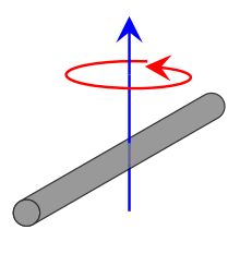
The columns of the rotation matrix define the directions of the principal axes of the body, and the constants , , and are called the principal moments of inertia. This result was first shown by J. J. Sylvester (1852), and is a form of Sylvester's law of inertia.[29][30] The principal axis with the highest moment of inertia is sometimes called the figure axis or axis of figure.
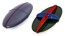
A toy top is an example of a rotating rigid body, and the word top is used in the names of types of rigid bodies. When all principal moments of inertia are distinct, the principal axes through center of mass are uniquely specified and the rigid body is called an asymmetric top. If two principal moments are the same, the rigid body is called a symmetric top and there is no unique choice for the two corresponding principal axes. If all three principal moments are the same, the rigid body is called a spherical top (although it need not be spherical) and any axis can be considered a principal axis, meaning that the moment of inertia is the same about any axis.
The principal axes are often aligned with the object's symmetry axes. If a rigid body has an axis of symmetry of order , meaning it is symmetrical under rotations of 360°/m about the given axis, that axis is a principal axis. When , the rigid body is a symmetric top. If a rigid body has at least two symmetry axes that are not parallel or perpendicular to each other, it is a spherical top, for example, a cube or any other Platonic solid.
The motion of vehicles is often described in terms of yaw, pitch, and roll which usually correspond approximately to rotations about the three principal axes. If the vehicle has bilateral symmetry then one of the principal axes will correspond exactly to the transverse (pitch) axis.
A practical example of this mathematical phenomenon is the routine automotive task of balancing a tire, which basically means adjusting the distribution of mass of a car wheel such that its principal axis of inertia is aligned with the axle so the wheel does not wobble.
An ellipsoid with the semi-principal diameters labelled , , and .
The moment of inertia matrix in body-frame coordinates is a quadratic form that defines a surface in the body called Poinsot's ellipsoid.[31] Let be the inertia matrix relative to the center of mass aligned with the principal axes, then the surface
or
defines an ellipsoid in the body frame. Write this equation in the form,
to see that the semi-principal diameters of this ellipsoid are given by
Let a point on this ellipsoid be defined in terms of its magnitude and direction, , where is a unit vector. Then the relationship presented above, between the inertia matrix and the scalar moment of inertia around an axis in the direction , yields
Thus, the magnitude of a point in the direction on the inertia ellipsoid is
^Escudier, Marcel; Atkins, Tony (2019). A Dictionary of Mechanical Engineering (2 ed.). Oxford University Press. doi:10.1093/acref/9780198832102.001.0001. ISBN 978-0-19-883210-2.
^ abMach, Ernst (1919). The Science of Mechanics. pp. 173–187. Retrieved November 21, 2014.
^Euler, Leonhard (1765). Theoria motus corporum solidorum seu rigidorum: Ex primis nostrae cognitionis principiis stabilita et ad omnes motus, qui in huiusmodi corpora cadere possunt, accommodata [The theory of motion of solid or rigid bodies: established from first principles of our knowledge and appropriate for all motions which can occur in such bodies.] (in Latin). Rostock and Greifswald (Germany): A. F. Röse. p. 166. ISBN 978-1-4297-4281-8. From page 166: "Definitio 7. 422. Momentum inertiae corporis respectu eujuspiam axis est summa omnium productorum, quae oriuntur, si singula corporis elementa per quadrata distantiarum suarum ab axe multiplicentur." (Definition 7. 422. A body's moment of inertia with respect to any axis is the sum of all of the products, which arise, if the individual elements of the body are multiplied by the square of their distances from the axis.)
^ abcdefMarion, JB; Thornton, ST (1995). Classical dynamics of particles & systems (4th ed.). Thomson. ISBN 0-03-097302-3.
^ abSymon, KR (1971). Mechanics (3rd ed.). Addison-Wesley. ISBN 0-201-07392-7.
^ abTenenbaum, RA (2004). Fundamentals of Applied Dynamics. Springer. ISBN 0-387-00887-X.
^ abcdefgh
Kane, T. R.; Levinson, D. A. (1985). Dynamics, Theory and Applications. New York: McGraw-Hill.
^ abWinn, Will (2010). Introduction to Understandable Physics: Volume I - Mechanics. AuthorHouse. p. 10.10. ISBN 978-1449063337.
^ abFullerton, Dan (2011). Honors Physics Essentials. Silly Beagle Productions. pp. 142–143. ISBN 978-0983563334.
^Wolfram, Stephen (2014). "Spinning Ice Skater". Wolfram Demonstrations Project. Mathematica, Inc. Retrieved September 30, 2014.
^Hokin, Samuel (2014). "Figure Skating Spins". The Physics of Everyday Stuff. Retrieved September 30, 2014.
^Breithaupt, Jim (2000). New Understanding Physics for Advanced Level. Nelson Thomas. p. 64. ISBN 0748743146.
^Crowell, Benjamin (2003). Conservation Laws. Light and Matter. pp. 107. ISBN 0970467028. ice skater conservation of angular momentum.
^Tipler, Paul A. (1999). Physics for Scientists and Engineers, Vol. 1: Mechanics, Oscillations and Waves, Thermodynamics. Macmillan. p. 304. ISBN 1572594918.
^ abcde
Paul, Burton (June 1979). Kinematics and Dynamics of Planar Machinery. Prentice Hall. ISBN 978-0135160626.
^
Halliday, David; Resnick, Robert; Walker, Jearl (2005). Fundamentals of physics (7th ed.). Hoboken, NJ: Wiley. ISBN 9780471216438.
^
French, A.P. (1971). Vibrations and waves. Boca Raton, FL: CRC Press. ISBN 9780748744473.
^ abcdef
Uicker, John J.; Pennock, Gordon R.; Shigley, Joseph E. (2010). Theory of Machines and Mechanisms (4th ed.). Oxford University Press. ISBN 978-0195371239.
^C. Couch and J. Mayes, Trifilar Pendulum for MOI, Happresearch.com, 2016.
^Gracey, William, The experimental determination of the moments of inertia of airplanes by a simplified compound-pendulum method, NACA Technical Note No. 1629, 1948
^Morrow, H. W.; Kokernak, Robert (2011). Statics and Strengths of Materials (7 ed.). New Jersey: Prentice Hall. pp. 192–196. ISBN 978-0135034521.
^In that situation this moment of inertia only describes how a torque applied along that axis causes a rotation about that axis. But, torques not aligned along a principal axis will also cause rotations about other axes.
^ abcdefghiFerdinand P. Beer; E. Russell Johnston, Jr.; Phillip J. Cornwell (2010). Vector mechanics for engineers: Dynamics (9th ed.). Boston: McGraw-Hill. ISBN 978-0077295493.
^Walter D. Pilkey, Analysis and Design of Elastic Beams: Computational Methods, John Wiley, 2002.
^ abGoldstein, H. (1980). Classical Mechanics (2nd ed.). Addison-Wesley. ISBN 0-201-02918-9.
^L. D. Landau and E. M. Lifshitz, Mechanics, Vol 1. 2nd Ed., Pergamon Press, 1969.
^L. W. Tsai, Robot Analysis: The mechanics of serial and parallel manipulators, John-Wiley, NY, 1999.
^David, Baraff. "Physically Based Modeling - Rigid Body Simulation" (PDF). Pixar Graphics Technologies.
^Sylvester, J J (1852). "A demonstration of the theorem that every homogeneous quadratic polynomial is reducible by real orthogonal substitutions to the form of a sum of positive and negative squares" (PDF). Philosophical Magazine. 4th Series. 4 (23): 138–142. doi:10.1080/14786445208647087. Retrieved June 27, 2008.


![{\displaystyle {\begin{aligned}I_{C,{\text{ball}}}&=\int _{-R}^{R}{\tfrac {1}{2}}\pi \rho r(z)^{4}\,dz=\int _{-R}^{R}{\tfrac {1}{2}}\pi \rho \left(R^{2}-z^{2}\right)^{2}\,dz\\[1ex]&={\tfrac {1}{2}}\pi \rho \left[R^{4}z-{\tfrac {2}{3}}R^{2}z^{3}+{\tfrac {1}{5}}z^{5}\right]_{-R}^{R}\\[1ex]&=\pi \rho \left(1-{\tfrac {2}{3}}+{\tfrac {1}{5}}\right)R^{5}\\[1ex]&={\tfrac {2}{5}}mR^{2},\end{aligned}}}](https://wikimedia.org/api/rest_v1/media/math/render/svg/34efa89e89894e1b5f5b3b9b981a790247d89411)


![{\displaystyle \left[\mathbf {b} \right]}](https://wikimedia.org/api/rest_v1/media/math/render/svg/2ce9643510bd433e0ed612edd5d3a9ed7faecfec)

![{\displaystyle {\begin{aligned}\mathbf {b} \times \mathbf {y} &\equiv \left[\mathbf {b} \right]\mathbf {y} \\\left[\mathbf {b} \right]&\equiv {\begin{bmatrix}0&-b_{z}&b_{y}\\b_{z}&0&-b_{x}\\-b_{y}&b_{x}&0\end{bmatrix}}.\end{aligned}}}](https://wikimedia.org/api/rest_v1/media/math/render/svg/b4782eb664e98a6d680dd96b77601ff9bc12ab4a)


![{\displaystyle [\Delta \mathbf {r} _{i}]}](https://wikimedia.org/api/rest_v1/media/math/render/svg/3ee5960e77611f673ab2f2050f356dbf0e403132)

![{\displaystyle \mathbf {L} =\left(-\sum _{i=1}^{n}m_{i}\left[\Delta \mathbf {r} _{i}\right]^{2}\right){\boldsymbol {\omega }}=\mathbf {I} _{\mathbf {C} }{\boldsymbol {\omega }},}](https://wikimedia.org/api/rest_v1/media/math/render/svg/26ff4f4ab9aa3fff11085b8828fc71a4af7de700)

![{\displaystyle \mathbf {I} _{\mathbf {C} }=-\sum _{i=1}^{n}m_{i}\left[\Delta \mathbf {r} _{i}\right]^{2},}](https://wikimedia.org/api/rest_v1/media/math/render/svg/6766e8a9ce07ff8f32ec86aaa929f1e5a3ce1a21)


![{\displaystyle {\begin{aligned}E_{\text{K}}&={\frac {1}{2}}\left(\sum _{i=1}^{n}m_{i}\left(\left[\Delta \mathbf {r} _{i}\right]{\boldsymbol {\omega }}\right)\cdot \left(\left[\Delta \mathbf {r} _{i}\right]{\boldsymbol {\omega }}\right)\right)+{\frac {1}{2}}\left(\sum _{i=1}^{n}m_{i}\right)\mathbf {V} _{\mathbf {C} }\cdot \mathbf {V} _{\mathbf {C} }\\&={\frac {1}{2}}\left(\sum _{i=1}^{n}m_{i}\left({\boldsymbol {\omega }}^{\mathsf {T}}\left[\Delta \mathbf {r} _{i}\right]^{\mathsf {T}}\left[\Delta \mathbf {r} _{i}\right]{\boldsymbol {\omega }}\right)\right)+{\frac {1}{2}}\left(\sum _{i=1}^{n}m_{i}\right)\mathbf {V} _{\mathbf {C} }\cdot \mathbf {V} _{\mathbf {C} }\\&={\frac {1}{2}}{\boldsymbol {\omega }}\cdot \left(-\sum _{i=1}^{n}m_{i}\left[\Delta \mathbf {r} _{i}\right]^{2}\right){\boldsymbol {\omega }}+{\frac {1}{2}}\left(\sum _{i=1}^{n}m_{i}\right)\mathbf {V} _{\mathbf {C} }\cdot \mathbf {V} _{\mathbf {C} }.\end{aligned}}}](https://wikimedia.org/api/rest_v1/media/math/render/svg/2c246c5646e149b67a600084c164f154ec7dda89)


![{\displaystyle \left[\Delta \mathbf {r} _{i}\right]=\left[\mathbf {r} _{i}-\mathbf {C} \right]}](https://wikimedia.org/api/rest_v1/media/math/render/svg/9b83ab9af0efe0f59204a493b10b5eb453594c19)

![{\displaystyle {\boldsymbol {\tau }}=\left(-\sum _{i=1}^{n}m_{i}\left[\Delta \mathbf {r} _{i}\right]^{2}\right){\boldsymbol {\alpha }}+{\boldsymbol {\omega }}\times \left(-\sum _{i=1}^{n}m_{i}\left[\Delta \mathbf {r} _{i}\right]^{2}\right){\boldsymbol {\omega }}}](https://wikimedia.org/api/rest_v1/media/math/render/svg/b93d7ec560fb15fbaaba36a2fd0869da807fd92e)

![{\displaystyle {\begin{aligned}{\boldsymbol {\tau }}&=\sum _{i=1}^{n}(\mathbf {r_{i}} -\mathbf {R} )\times (m_{i}\mathbf {a} _{i})\\&=\sum _{i=1}^{n}\Delta \mathbf {r} _{i}\times (m_{i}\mathbf {a} _{i})\\&=\sum _{i=1}^{n}m_{i}[\Delta \mathbf {r} _{i}\times \mathbf {a} _{i}]\;\ldots {\text{ cross-product scalar multiplication}}\\&=\sum _{i=1}^{n}m_{i}[\Delta \mathbf {r} _{i}\times (\mathbf {a} _{{\text{tangential}},i}+\mathbf {a} _{{\text{centripetal}},i}+\mathbf {A} _{\mathbf {R} })]\\&=\sum _{i=1}^{n}m_{i}[\Delta \mathbf {r} _{i}\times (\mathbf {a} _{{\text{tangential}},i}+\mathbf {a} _{{\text{centripetal}},i}+0)]\\\end{aligned}}}](https://wikimedia.org/api/rest_v1/media/math/render/svg/e8f0c3e85512d4f04a615d04c2c28e855fbf2120)

![{\displaystyle {\begin{aligned}{\boldsymbol {\tau }}&=\sum _{i=1}^{n}m_{i}[\Delta \mathbf {r} _{i}\times \mathbf {a} _{{\text{tangential}},i}+\Delta \mathbf {r} _{i}\times \mathbf {a} _{{\text{centripetal}},i}]\\{\boldsymbol {\tau }}&=\sum _{i=1}^{n}m_{i}[\Delta \mathbf {r} _{i}\times ({\boldsymbol {\alpha }}\times \Delta \mathbf {r} _{i})+\Delta \mathbf {r} _{i}\times ({\boldsymbol {\omega }}\times \mathbf {v} _{{\text{tangential}},i})]\\{\boldsymbol {\tau }}&=\sum _{i=1}^{n}m_{i}[\Delta \mathbf {r} _{i}\times ({\boldsymbol {\alpha }}\times \Delta \mathbf {r} _{i})+\Delta \mathbf {r} _{i}\times ({\boldsymbol {\omega }}\times ({\boldsymbol {\omega }}\times \Delta \mathbf {r} _{i}))]\end{aligned}}}](https://wikimedia.org/api/rest_v1/media/math/render/svg/92a8c5e71419b6391fce82b173f4ca48bf2896af)
![{\displaystyle {\begin{aligned}0&=\Delta \mathbf {r} _{i}\times ({\boldsymbol {\omega }}\times ({\boldsymbol {\omega }}\times \Delta \mathbf {r} _{i}))+{\boldsymbol {\omega }}\times (({\boldsymbol {\omega }}\times \Delta \mathbf {r} _{i})\times \Delta \mathbf {r} _{i})+({\boldsymbol {\omega }}\times \Delta \mathbf {r} _{i})\times (\Delta \mathbf {r} _{i}\times {\boldsymbol {\omega }})\\&=\Delta \mathbf {r} _{i}\times ({\boldsymbol {\omega }}\times ({\boldsymbol {\omega }}\times \Delta \mathbf {r} _{i}))+{\boldsymbol {\omega }}\times (({\boldsymbol {\omega }}\times \Delta \mathbf {r} _{i})\times \Delta \mathbf {r} _{i})+({\boldsymbol {\omega }}\times \Delta \mathbf {r} _{i})\times -({\boldsymbol {\omega }}\times \Delta \mathbf {r} _{i})\;\ldots {\text{ cross-product anticommutativity}}\\&=\Delta \mathbf {r} _{i}\times ({\boldsymbol {\omega }}\times ({\boldsymbol {\omega }}\times \Delta \mathbf {r} _{i}))+{\boldsymbol {\omega }}\times (({\boldsymbol {\omega }}\times \Delta \mathbf {r} _{i})\times \Delta \mathbf {r} _{i})+-[({\boldsymbol {\omega }}\times \Delta \mathbf {r} _{i})\times ({\boldsymbol {\omega }}\times \Delta \mathbf {r} _{i})]\;\ldots {\text{ cross-product scalar multiplication}}\\&=\Delta \mathbf {r} _{i}\times ({\boldsymbol {\omega }}\times ({\boldsymbol {\omega }}\times \Delta \mathbf {r} _{i}))+{\boldsymbol {\omega }}\times (({\boldsymbol {\omega }}\times \Delta \mathbf {r} _{i})\times \Delta \mathbf {r} _{i})+-[0]\;\ldots {\text{ self cross-product}}\\0&=\Delta \mathbf {r} _{i}\times ({\boldsymbol {\omega }}\times ({\boldsymbol {\omega }}\times \Delta \mathbf {r} _{i}))+{\boldsymbol {\omega }}\times (({\boldsymbol {\omega }}\times \Delta \mathbf {r} _{i})\times \Delta \mathbf {r} _{i})\end{aligned}}}](https://wikimedia.org/api/rest_v1/media/math/render/svg/1faaf09eaed98f82dc96bf237ef4bdd7921d0f88)
![{\displaystyle {\begin{aligned}\Delta \mathbf {r} _{i}\times ({\boldsymbol {\omega }}\times ({\boldsymbol {\omega }}\times \Delta \mathbf {r} _{i}))&=-[{\boldsymbol {\omega }}\times (({\boldsymbol {\omega }}\times \Delta \mathbf {r} _{i})\times \Delta \mathbf {r} _{i})]\\&=-[({\boldsymbol {\omega }}\times \Delta \mathbf {r} _{i})({\boldsymbol {\omega }}\cdot \Delta \mathbf {r} _{i})-\Delta \mathbf {r} _{i}({\boldsymbol {\omega }}\cdot ({\boldsymbol {\omega }}\times \Delta \mathbf {r} _{i}))]\;\ldots {\text{ vector triple product}}\\&=-[({\boldsymbol {\omega }}\times \Delta \mathbf {r} _{i})({\boldsymbol {\omega }}\cdot \Delta \mathbf {r} _{i})-\Delta \mathbf {r} _{i}(\Delta \mathbf {r} _{i}\cdot ({\boldsymbol {\omega }}\times {\boldsymbol {\omega }}))]\;\ldots {\text{ scalar triple product}}\\&=-[({\boldsymbol {\omega }}\times \Delta \mathbf {r} _{i})({\boldsymbol {\omega }}\cdot \Delta \mathbf {r} _{i})-\Delta \mathbf {r} _{i}(\Delta \mathbf {r} _{i}\cdot (0))]\;\ldots {\text{ self cross-product}}\\&=-[({\boldsymbol {\omega }}\times \Delta \mathbf {r} _{i})({\boldsymbol {\omega }}\cdot \Delta \mathbf {r} _{i})]\\&=-[{\boldsymbol {\omega }}\times (\Delta \mathbf {r} _{i}({\boldsymbol {\omega }}\cdot \Delta \mathbf {r} _{i}))]\;\ldots {\text{ cross-product scalar multiplication}}\\&={\boldsymbol {\omega }}\times -(\Delta \mathbf {r} _{i}({\boldsymbol {\omega }}\cdot \Delta \mathbf {r} _{i}))\;\ldots {\text{ cross-product scalar multiplication}}\\\Delta \mathbf {r} _{i}\times ({\boldsymbol {\omega }}\times ({\boldsymbol {\omega }}\times \Delta \mathbf {r} _{i}))&={\boldsymbol {\omega }}\times -(\Delta \mathbf {r} _{i}(\Delta \mathbf {r} _{i}\cdot {\boldsymbol {\omega }}))\;\ldots {\text{ dot-product commutativity}}\\\end{aligned}}}](https://wikimedia.org/api/rest_v1/media/math/render/svg/64290822854e10ddee72f763b816c319e88c257a)
![{\displaystyle {\begin{aligned}{\boldsymbol {\tau }}&=\sum _{i=1}^{n}m_{i}[\Delta \mathbf {r} _{i}\times ({\boldsymbol {\alpha }}\times \Delta \mathbf {r} _{i})+\Delta \mathbf {r} _{i}\times ({\boldsymbol {\omega }}\times ({\boldsymbol {\omega }}\times \Delta \mathbf {r} _{i}))]\\&=\sum _{i=1}^{n}m_{i}[\Delta \mathbf {r} _{i}\times ({\boldsymbol {\alpha }}\times \Delta \mathbf {r} _{i})+{\boldsymbol {\omega }}\times -(\Delta \mathbf {r} _{i}(\Delta \mathbf {r} _{i}\cdot {\boldsymbol {\omega }}))]\\&=\sum _{i=1}^{n}m_{i}[\Delta \mathbf {r} _{i}\times ({\boldsymbol {\alpha }}\times \Delta \mathbf {r} _{i})+{\boldsymbol {\omega }}\times \{0-\Delta \mathbf {r} _{i}(\Delta \mathbf {r} _{i}\cdot {\boldsymbol {\omega }})\}]\\&=\sum _{i=1}^{n}m_{i}[\Delta \mathbf {r} _{i}\times ({\boldsymbol {\alpha }}\times \Delta \mathbf {r} _{i})+{\boldsymbol {\omega }}\times \{[{\boldsymbol {\omega }}(\Delta \mathbf {r} _{i}\cdot \Delta \mathbf {r} _{i})-{\boldsymbol {\omega }}(\Delta \mathbf {r} _{i}\cdot \Delta \mathbf {r} _{i})]-\Delta \mathbf {r} _{i}(\Delta \mathbf {r} _{i}\cdot {\boldsymbol {\omega }})\}]\;\ldots \;{\boldsymbol {\omega }}(\Delta \mathbf {r} _{i}\cdot \Delta \mathbf {r} _{i})-{\boldsymbol {\omega }}(\Delta \mathbf {r} _{i}\cdot \Delta \mathbf {r} _{i})=0\\&=\sum _{i=1}^{n}m_{i}[\Delta \mathbf {r} _{i}\times ({\boldsymbol {\alpha }}\times \Delta \mathbf {r} _{i})+{\boldsymbol {\omega }}\times \{[{\boldsymbol {\omega }}(\Delta \mathbf {r} _{i}\cdot \Delta \mathbf {r} _{i})-\Delta \mathbf {r} _{i}(\Delta \mathbf {r} _{i}\cdot {\boldsymbol {\omega }})]-{\boldsymbol {\omega }}(\Delta \mathbf {r} _{i}\cdot \Delta \mathbf {r} _{i})\}]\;\ldots {\text{ addition associativity}}\\\end{aligned}}}](https://wikimedia.org/api/rest_v1/media/math/render/svg/870182ea378ff573ef3abb446dfb868374252fd2)
![{\displaystyle {\begin{aligned}{\boldsymbol {\tau }}&=\sum _{i=1}^{n}m_{i}[\Delta \mathbf {r} _{i}\times ({\boldsymbol {\alpha }}\times \Delta \mathbf {r} _{i})+{\boldsymbol {\omega }}\times \{{\boldsymbol {\omega }}(\Delta \mathbf {r} _{i}\cdot \Delta \mathbf {r} _{i})-\Delta \mathbf {r} _{i}(\Delta \mathbf {r} _{i}\cdot {\boldsymbol {\omega }})\}-{\boldsymbol {\omega }}\times {\boldsymbol {\omega }}(\Delta \mathbf {r} _{i}\cdot \Delta \mathbf {r} _{i})]\;\ldots {\text{ cross-product distributivity over addition}}\\&=\sum _{i=1}^{n}m_{i}[\Delta \mathbf {r} _{i}\times ({\boldsymbol {\alpha }}\times \Delta \mathbf {r} _{i})+{\boldsymbol {\omega }}\times \{{\boldsymbol {\omega }}(\Delta \mathbf {r} _{i}\cdot \Delta \mathbf {r} _{i})-\Delta \mathbf {r} _{i}(\Delta \mathbf {r} _{i}\cdot {\boldsymbol {\omega }})\}-(\Delta \mathbf {r} _{i}\cdot \Delta \mathbf {r} _{i})({\boldsymbol {\omega }}\times {\boldsymbol {\omega }})]\;\ldots {\text{ cross-product scalar multiplication}}\\&=\sum _{i=1}^{n}m_{i}[\Delta \mathbf {r} _{i}\times ({\boldsymbol {\alpha }}\times \Delta \mathbf {r} _{i})+{\boldsymbol {\omega }}\times \{{\boldsymbol {\omega }}(\Delta \mathbf {r} _{i}\cdot \Delta \mathbf {r} _{i})-\Delta \mathbf {r} _{i}(\Delta \mathbf {r} _{i}\cdot {\boldsymbol {\omega }})\}-(\Delta \mathbf {r} _{i}\cdot \Delta \mathbf {r} _{i})(0)]\;\ldots {\text{ self cross-product}}\\&=\sum _{i=1}^{n}m_{i}[\Delta \mathbf {r} _{i}\times ({\boldsymbol {\alpha }}\times \Delta \mathbf {r} _{i})+{\boldsymbol {\omega }}\times \{{\boldsymbol {\omega }}(\Delta \mathbf {r} _{i}\cdot \Delta \mathbf {r} _{i})-\Delta \mathbf {r} _{i}(\Delta \mathbf {r} _{i}\cdot {\boldsymbol {\omega }})\}]\\&=\sum _{i=1}^{n}m_{i}[\Delta \mathbf {r} _{i}\times ({\boldsymbol {\alpha }}\times \Delta \mathbf {r} _{i})+{\boldsymbol {\omega }}\times \{\Delta \mathbf {r} _{i}\times ({\boldsymbol {\omega }}\times \Delta \mathbf {r} _{i})\}]\;\ldots {\text{ vector triple product}}\\&=\sum _{i=1}^{n}m_{i}[\Delta \mathbf {r} _{i}\times -(\Delta \mathbf {r} _{i}\times {\boldsymbol {\alpha }})+{\boldsymbol {\omega }}\times \{\Delta \mathbf {r} _{i}\times -(\Delta \mathbf {r} _{i}\times {\boldsymbol {\omega }})\}]\;\ldots {\text{ cross-product anticommutativity}}\\&=-\sum _{i=1}^{n}m_{i}[\Delta \mathbf {r} _{i}\times (\Delta \mathbf {r} _{i}\times {\boldsymbol {\alpha }})+{\boldsymbol {\omega }}\times \{\Delta \mathbf {r} _{i}\times (\Delta \mathbf {r} _{i}\times {\boldsymbol {\omega }})\}]\;\ldots {\text{ cross-product scalar multiplication}}\\&=-\sum _{i=1}^{n}m_{i}[\Delta \mathbf {r} _{i}\times (\Delta \mathbf {r} _{i}\times {\boldsymbol {\alpha }})]+-\sum _{i=1}^{n}m_{i}[{\boldsymbol {\omega }}\times \{\Delta \mathbf {r} _{i}\times (\Delta \mathbf {r} _{i}\times {\boldsymbol {\omega }})\}]\;\ldots {\text{ summation distributivity}}\\{\boldsymbol {\tau }}&=-\sum _{i=1}^{n}m_{i}[\Delta \mathbf {r} _{i}\times (\Delta \mathbf {r} _{i}\times {\boldsymbol {\alpha }})]+{\boldsymbol {\omega }}\times -\sum _{i=1}^{n}m_{i}[\Delta \mathbf {r} _{i}\times (\Delta \mathbf {r} _{i}\times {\boldsymbol {\omega }})]\;\ldots \;{\boldsymbol {\omega }}{\text{ is not characteristic of particle }}P_{i}\end{aligned}}}](https://wikimedia.org/api/rest_v1/media/math/render/svg/85585a7db797b2d9747d752c2c5b54578da2dd71)

![{\displaystyle {\begin{aligned}-\sum _{i=1}^{n}m_{i}[\Delta \mathbf {r} _{i}\times (\Delta \mathbf {r} _{i}\times \mathbf {u} )]&=-\sum _{i=1}^{n}m_{i}\left({\begin{bmatrix}0&-\Delta r_{3,i}&\Delta r_{2,i}\\\Delta r_{3,i}&0&-\Delta r_{1,i}\\-\Delta r_{2,i}&\Delta r_{1,i}&0\end{bmatrix}}\left({\begin{bmatrix}0&-\Delta r_{3,i}&\Delta r_{2,i}\\\Delta r_{3,i}&0&-\Delta r_{1,i}\\-\Delta r_{2,i}&\Delta r_{1,i}&0\end{bmatrix}}{\begin{bmatrix}u_{1}\\u_{2}\\u_{3}\end{bmatrix}}\right)\right)\;\ldots {\text{ cross-product as matrix multiplication}}\\[6pt]&=-\sum _{i=1}^{n}m_{i}\left({\begin{bmatrix}0&-\Delta r_{3,i}&\Delta r_{2,i}\\\Delta r_{3,i}&0&-\Delta r_{1,i}\\-\Delta r_{2,i}&\Delta r_{1,i}&0\end{bmatrix}}{\begin{bmatrix}-\Delta r_{3,i}\,u_{2}+\Delta r_{2,i}\,u_{3}\\+\Delta r_{3,i}\,u_{1}-\Delta r_{1,i}\,u_{3}\\-\Delta r_{2,i}\,u_{1}+\Delta r_{1,i}\,u_{2}\end{bmatrix}}\right)\\[6pt]&=-\sum _{i=1}^{n}m_{i}{\begin{bmatrix}-\Delta r_{3,i}(+\Delta r_{3,i}\,u_{1}-\Delta r_{1,i}\,u_{3})+\Delta r_{2,i}(-\Delta r_{2,i}\,u_{1}+\Delta r_{1,i}\,u_{2})\\+\Delta r_{3,i}(-\Delta r_{3,i}\,u_{2}+\Delta r_{2,i}\,u_{3})-\Delta r_{1,i}(-\Delta r_{2,i}\,u_{1}+\Delta r_{1,i}\,u_{2})\\-\Delta r_{2,i}(-\Delta r_{3,i}\,u_{2}+\Delta r_{2,i}\,u_{3})+\Delta r_{1,i}(+\Delta r_{3,i}\,u_{1}-\Delta r_{1,i}\,u_{3})\end{bmatrix}}\\[6pt]&=-\sum _{i=1}^{n}m_{i}{\begin{bmatrix}-\Delta r_{3,i}^{2}\,u_{1}+\Delta r_{1,i}\Delta r_{3,i}\,u_{3}-\Delta r_{2,i}^{2}\,u_{1}+\Delta r_{1,i}\Delta r_{2,i}\,u_{2}\\-\Delta r_{3,i}^{2}\,u_{2}+\Delta r_{2,i}\Delta r_{3,i}\,u_{3}+\Delta r_{2,i}\Delta r_{1,i}\,u_{1}-\Delta r_{1,i}^{2}\,u_{2}\\+\Delta r_{3,i}\Delta r_{2,i}\,u_{2}-\Delta r_{2,i}^{2}\,u_{3}+\Delta r_{3,i}\Delta r_{1,i}\,u_{1}-\Delta r_{1,i}^{2}\,u_{3}\end{bmatrix}}\\[6pt]&=-\sum _{i=1}^{n}m_{i}{\begin{bmatrix}-(\Delta r_{2,i}^{2}+\Delta r_{3,i}^{2})\,u_{1}+\Delta r_{1,i}\Delta r_{2,i}\,u_{2}+\Delta r_{1,i}\Delta r_{3,i}\,u_{3}\\+\Delta r_{2,i}\Delta r_{1,i}\,u_{1}-(\Delta r_{1,i}^{2}+\Delta r_{3,i}^{2})\,u_{2}+\Delta r_{2,i}\Delta r_{3,i}\,u_{3}\\+\Delta r_{3,i}\Delta r_{1,i}\,u_{1}+\Delta r_{3,i}\Delta r_{2,i}\,u_{2}-(\Delta r_{1,i}^{2}+\Delta r_{2,i}^{2})\,u_{3}\end{bmatrix}}\\[6pt]&=-\sum _{i=1}^{n}m_{i}{\begin{bmatrix}-(\Delta r_{2,i}^{2}+\Delta r_{3,i}^{2})&\Delta r_{1,i}\Delta r_{2,i}&\Delta r_{1,i}\Delta r_{3,i}\\\Delta r_{2,i}\Delta r_{1,i}&-(\Delta r_{1,i}^{2}+\Delta r_{3,i}^{2})&\Delta r_{2,i}\Delta r_{3,i}\\\Delta r_{3,i}\Delta r_{1,i}&\Delta r_{3,i}\Delta r_{2,i}&-(\Delta r_{1,i}^{2}+\Delta r_{2,i}^{2})\end{bmatrix}}{\begin{bmatrix}u_{1}\\u_{2}\\u_{3}\end{bmatrix}}\\&=-\sum _{i=1}^{n}m_{i}[\Delta r_{i}]^{2}\mathbf {u} \\[6pt]-\sum _{i=1}^{n}m_{i}[\Delta \mathbf {r} _{i}\times (\Delta \mathbf {r} _{i}\times \mathbf {u} )]&=\left(-\sum _{i=1}^{n}m_{i}[\Delta r_{i}]^{2}\right)\mathbf {u} \;\ldots \;\mathbf {u} {\text{ is not characteristic of }}P_{i}\end{aligned}}}](https://wikimedia.org/api/rest_v1/media/math/render/svg/ef0bb9597377649b0d39c7b8e75fa2f880df2e23)
![{\displaystyle {\begin{aligned}{\boldsymbol {\tau }}&=-\sum _{i=1}^{n}m_{i}[\Delta \mathbf {r} _{i}\times (\Delta \mathbf {r} _{i}\times {\boldsymbol {\alpha }})]+{\boldsymbol {\omega }}\times -\sum _{i=1}^{n}m_{i}\Delta \mathbf {r} _{i}\times (\Delta \mathbf {r} _{i}\times {\boldsymbol {\omega }})]\\&=\left(-\sum _{i=1}^{n}m_{i}[\Delta r_{i}]^{2}\right){\boldsymbol {\alpha }}+{\boldsymbol {\omega }}\times \left(-\sum _{i=1}^{n}m_{i}[\Delta r_{i}]^{2}\right){\boldsymbol {\omega }}\end{aligned}}}](https://wikimedia.org/api/rest_v1/media/math/render/svg/24eed2971eccd0e0b63f32600e1d3fc6254dca49)


![{\displaystyle \mathbf {I} _{\mathbf {R} }=-\sum _{i=1}^{n}m_{i}\left[\mathbf {r} _{i}-\mathbf {R} \right]^{2}.}](https://wikimedia.org/api/rest_v1/media/math/render/svg/93e62233b3acff4fc919fc24e8d6241551543087)


![{\displaystyle \mathbf {I} _{\mathbf {R} }=-\sum _{i=1}^{n}m_{i}[\mathbf {r} _{i}-\left(\mathbf {C} +\mathbf {d} \right)]^{2}=-\sum _{i=1}^{n}m_{i}[\left(\mathbf {r} _{i}-\mathbf {C} \right)-\mathbf {d} ]^{2}.}](https://wikimedia.org/api/rest_v1/media/math/render/svg/0063409d605348215928372e62f294287f06fb98)
![{\displaystyle \mathbf {I} _{\mathbf {R} }=-\left(\sum _{i=1}^{n}m_{i}[\mathbf {r} _{i}-\mathbf {C} ]^{2}\right)+\left(\sum _{i=1}^{n}m_{i}[\mathbf {r} _{i}-\mathbf {C} ]\right)[\mathbf {d} ]+[\mathbf {d} ]\left(\sum _{i=1}^{n}m_{i}[\mathbf {r} _{i}-\mathbf {C} ]\right)-\left(\sum _{i=1}^{n}m_{i}\right)[\mathbf {d} ]^{2}.}](https://wikimedia.org/api/rest_v1/media/math/render/svg/68eee7fefe0e716823fd5d80384303b8aef58b99)
![{\displaystyle [\mathbf {d} ]}](https://wikimedia.org/api/rest_v1/media/math/render/svg/a5785dcf9605fb6ace7c1a8c8b4d6b365af48366)
![{\displaystyle \mathbf {I} _{\mathbf {R} }=\mathbf {I} _{\mathbf {C} }-M[\mathbf {d} ]^{2},}](https://wikimedia.org/api/rest_v1/media/math/render/svg/1c59b0848c4b1d69fff75c4257005225cd42c74d)
![{\displaystyle -m\left[\mathbf {r} \right]^{2}}](https://wikimedia.org/api/rest_v1/media/math/render/svg/6b3ed54432828b43d6ae23e9a2e9c009c7336024)
![{\displaystyle m\left[\mathbf {r} \right]^{\mathsf {T}}\left[\mathbf {r} \right]}](https://wikimedia.org/api/rest_v1/media/math/render/svg/27fed5e06e85cd3d74847c333b7a32cbd6a31fe7)
![{\displaystyle [\mathbf {r} ]}](https://wikimedia.org/api/rest_v1/media/math/render/svg/ba4c4e0b7a62e35392117d1331b60c9e3276b5c9)

![{\displaystyle I_{L}=\mathbf {\hat {k}} \cdot \left(-\sum _{i=1}^{N}m_{i}\left[\Delta \mathbf {r} _{i}\right]^{2}\right)\mathbf {\hat {k}} =\mathbf {\hat {k}} \cdot \mathbf {I} _{\mathbf {R} }\mathbf {\hat {k}} =\mathbf {\hat {k}} ^{\mathsf {T}}\mathbf {I} _{\mathbf {R} }\mathbf {\hat {k}} ,}](https://wikimedia.org/api/rest_v1/media/math/render/svg/78bb7c062959fd615347939341b32bf66de221c6)


![{\displaystyle \left[\mathbf {\hat {k}} \right]}](https://wikimedia.org/api/rest_v1/media/math/render/svg/a515c7495954477be07dee4f29d4c4c4ec50cf98)
![{\displaystyle \left[\mathbf {\hat {k}} \right]\mathbf {y} =\mathbf {\hat {k}} \times \mathbf {y} }](https://wikimedia.org/api/rest_v1/media/math/render/svg/10d1281a399f50084c4d71e516f5d56b1cf5426f)
![{\displaystyle -\left[\mathbf {\hat {k}} \right]^{2}\equiv \left|\mathbf {\hat {k}} \right|^{2}\left(\mathbf {E} -\mathbf {\hat {k}} \mathbf {\hat {k}} ^{\mathsf {T}}\right)=\mathbf {E} -\mathbf {\hat {k}} \mathbf {\hat {k}} ^{\mathsf {T}},}](https://wikimedia.org/api/rest_v1/media/math/render/svg/d92be0b3adbb50fbe61b31dc0237f0fc102476a0)
![{\displaystyle {\begin{aligned}\left|\Delta \mathbf {r} _{i}^{\perp }\right|^{2}&=\left(-\left[\mathbf {\hat {k}} \right]^{2}\Delta \mathbf {r} _{i}\right)\cdot \left(-\left[\mathbf {\hat {k}} \right]^{2}\Delta \mathbf {r} _{i}\right)\\&=\left(\mathbf {\hat {k}} \times \left(\mathbf {\hat {k}} \times \Delta \mathbf {r} _{i}\right)\right)\cdot \left(\mathbf {\hat {k}} \times \left(\mathbf {\hat {k}} \times \Delta \mathbf {r} _{i}\right)\right)\end{aligned}}}](https://wikimedia.org/api/rest_v1/media/math/render/svg/9d205a6da935ecfa8f5e13feb1a930f1d032022a)

![{\displaystyle {\begin{aligned}&\left(\mathbf {\hat {k}} \times \left(\mathbf {\hat {k}} \times \Delta \mathbf {r} _{i}\right)\right)\cdot \left(\mathbf {\hat {k}} \times \left(\mathbf {\hat {k}} \times \Delta \mathbf {r} _{i}\right)\right)\\={}&\left(\left(\mathbf {\hat {k}} \times \left(\mathbf {\hat {k}} \times \Delta \mathbf {r} _{i}\right)\right)\times \mathbf {\hat {k}} \right)\cdot \left(\mathbf {\hat {k}} \times \Delta \mathbf {r} _{i}\right)\\={}&\left(\mathbf {\hat {k}} \times \Delta \mathbf {r} _{i}\right)\cdot \left(-\Delta \mathbf {r} _{i}\times \mathbf {\hat {k}} \right)\\={}&-\mathbf {\hat {k}} \cdot \left(\Delta \mathbf {r} _{i}\times \Delta \mathbf {r} _{i}\times \mathbf {\hat {k}} \right)\\={}&-\mathbf {\hat {k}} \cdot \left[\Delta \mathbf {r} _{i}\right]^{2}\mathbf {\hat {k}} .\end{aligned}}}](https://wikimedia.org/api/rest_v1/media/math/render/svg/62111ff66a6922e2705a7eb60478088077b7d9bf)
![{\displaystyle {\begin{aligned}I_{L}&=\sum _{i=1}^{N}m_{i}\left|\Delta \mathbf {r} _{i}^{\perp }\right|^{2}\\&=-\sum _{i=1}^{N}m_{i}\mathbf {\hat {k}} \cdot \left[\Delta \mathbf {r} _{i}\right]^{2}\mathbf {\hat {k}} =\mathbf {\hat {k}} \cdot \left(-\sum _{i=1}^{N}m_{i}\left[\Delta \mathbf {r} _{i}\right]^{2}\right)\mathbf {\hat {k}} \\&=\mathbf {\hat {k}} \cdot \mathbf {I} _{\mathbf {R} }\mathbf {\hat {k}} =\mathbf {\hat {k}} ^{\mathsf {T}}\mathbf {I} _{\mathbf {R} }\mathbf {\hat {k}} ,\end{aligned}}}](https://wikimedia.org/api/rest_v1/media/math/render/svg/1f4a4a61db87467a4b76294e68bba221a2810cdf)


![{\displaystyle [\mathbf {r} ]\mathbf {x} =\mathbf {r} \times \mathbf {x} }](https://wikimedia.org/api/rest_v1/media/math/render/svg/0f32ba1c18fa5966e4dcd2275a7f7e3bc21f6dc0)
![{\displaystyle \mathbf {I} =\iiint _{V}\rho (\mathbf {r} )[\mathbf {r} ]^{\textsf {T}}[\mathbf {r} ]\,dV=-\iiint _{Q}\rho (\mathbf {r} )[\mathbf {r} ]^{2}\,dV}](https://wikimedia.org/api/rest_v1/media/math/render/svg/3f468dc8f2e4246bf78b1916390083f90998be5c)


![{\displaystyle \mathbf {I} ={\begin{bmatrix}I_{11}&I_{12}&I_{13}\\[1.8ex]I_{21}&I_{22}&I_{23}\\[1.8ex]I_{31}&I_{32}&I_{33}\end{bmatrix}}={\begin{bmatrix}I_{xx}&I_{xy}&I_{xz}\\[1.8ex]I_{yx}&I_{yy}&I_{yz}\\[1.8ex]I_{zx}&I_{zy}&I_{zz}\end{bmatrix}}={\begin{bmatrix}\sum _{k=1}^{N}m_{k}\left(y_{k}^{2}+z_{k}^{2}\right)&-\sum _{k=1}^{N}m_{k}x_{k}y_{k}&-\sum _{k=1}^{N}m_{k}x_{k}z_{k}\\[1ex]-\sum _{k=1}^{N}m_{k}x_{k}y_{k}&\sum _{k=1}^{N}m_{k}\left(x_{k}^{2}+z_{k}^{2}\right)&-\sum _{k=1}^{N}m_{k}y_{k}z_{k}\\[1ex]-\sum _{k=1}^{N}m_{k}x_{k}z_{k}&-\sum _{k=1}^{N}m_{k}y_{k}z_{k}&\sum _{k=1}^{N}m_{k}\left(x_{k}^{2}+y_{k}^{2}\right)\end{bmatrix}}.}](https://wikimedia.org/api/rest_v1/media/math/render/svg/300757855c441dbf4e1e9d36f1cd88dad29e5e8a)
![{\displaystyle {\begin{aligned}I_{xy}=I_{yx}\ &{\stackrel {\mathrm {def} }{=}}\ \sum _{k=1}^{N}m_{k}x_{k}y_{k},\\I_{xz}=I_{zx}\ &{\stackrel {\mathrm {def} }{=}}\ \sum _{k=1}^{N}m_{k}x_{k}z_{k},\\I_{yz}=I_{zy}\ &{\stackrel {\mathrm {def} }{=}}\ \sum _{k=1}^{N}m_{k}y_{k}z_{k},\\[3pt]\mathbf {I} ={\begin{bmatrix}I_{11}&I_{12}&I_{13}\\[1.8ex]I_{21}&I_{22}&I_{23}\\[1.8ex]I_{31}&I_{32}&I_{33}\end{bmatrix}}&={\begin{bmatrix}I_{xx}&-I_{xy}&-I_{xz}\\[1.8ex]-I_{yx}&I_{yy}&-I_{yz}\\[1.8ex]-I_{zx}&-I_{zy}&I_{zz}\end{bmatrix}}={\begin{bmatrix}\sum _{k=1}^{N}m_{k}\left(y_{k}^{2}+z_{k}^{2}\right)&-\sum _{k=1}^{N}m_{k}x_{k}y_{k}&-\sum _{k=1}^{N}m_{k}x_{k}z_{k}\\[1ex]-\sum _{k=1}^{N}m_{k}x_{k}y_{k}&\sum _{k=1}^{N}m_{k}\left(x_{k}^{2}+z_{k}^{2}\right)&-\sum _{k=1}^{N}m_{k}y_{k}z_{k}\\[1ex]-\sum _{k=1}^{N}m_{k}x_{k}z_{k}&-\sum _{k=1}^{N}m_{k}y_{k}z_{k}&\sum _{k=1}^{N}m_{k}\left(x_{k}^{2}+y_{k}^{2}\right)\end{bmatrix}}.\end{aligned}}}](https://wikimedia.org/api/rest_v1/media/math/render/svg/78eb9b0b4686b23e51350e74bb24511fce107f93)


![{\displaystyle I=m{\begin{bmatrix}n_{1}&n_{2}&n_{3}\end{bmatrix}}{\begin{bmatrix}y^{2}+z^{2}&-xy&-xz\\[0.5ex]-yx&x^{2}+z^{2}&-yz\\[0.5ex]-zx&-zy&x^{2}+y^{2}\end{bmatrix}}{\begin{bmatrix}n_{1}\\[0.7ex]n_{2}\\[0.7ex]n_{3}\end{bmatrix}}.}](https://wikimedia.org/api/rest_v1/media/math/render/svg/dfb30784bc5347a3bef70bf77ea6413725e1d4d7)

![{\displaystyle \mathbf {I} =\mathbf {I} _{0}+m[(\mathbf {R} \cdot \mathbf {R} )\mathbf {E} _{3}-\mathbf {R} \otimes \mathbf {R} ]}](https://wikimedia.org/api/rest_v1/media/math/render/svg/22568fa28674e243955b8fdddced7496b8e6487d)