


Summary
A magnetohydrodynamic generator (MHD generator) is a magnetohydrodynamic converter that transforms thermal energy and kinetic energy directly into electricity. An MHD generator, like a conventional generator, relies on moving a conductor through a magnetic field to generate electric current. The MHD generator uses hot conductive ionized gas (a plasma) as the moving conductor. The mechanical dynamo, in contrast, uses the motion of mechanical devices to accomplish this.
MHD generators are different from traditional electric generators in that they operate without moving parts (e.g. no turbine) to limit the upper temperature. They therefore have the highest known theoretical thermodynamic efficiency of any electrical generation method. MHD has been extensively developed as a topping cycle to increase the efficiency of electric generation, especially when burning coal or natural gas. The hot exhaust gas from an MHD generator can heat the boilers of a steam power plant, increasing overall efficiency.
Practical MHD generators have been developed for fossil fuels, but these were overtaken by less expensive combined cycles in which the exhaust of a gas turbine or molten carbonate fuel cell heats steam to power a steam turbine.
MHD dynamos are the complement of MHD accelerators, which have been applied to pump liquid metals, seawater, and plasmas.
Natural MHD dynamos are an active area of research in plasma physics and are of great interest to the geophysics and astrophysics communities since the magnetic fields of the Earth and Sun are produced by these natural dynamos.
Principle edit
The Lorentz Force Law describes the effects of a charged particle moving in a constant magnetic field. The simplest form of this law is given by the vector equation.

where
- F is the force acting on the particle.
- Q is the charge of the particle,
- v is the velocity of the particle, and
- B is the magnetic field.
The vector F is perpendicular to both v and B according to the right hand rule.
Power generation edit
Typically, for a large power station to approach the operational efficiency of computer models, steps must be taken to increase the electrical conductivity of the conductive substance. The heating of a gas to its plasma state or the addition of other easily ionizable substances like the salts of alkali metals can accomplish this increase. In practice, a number of issues must be considered in the implementation of an MHD generator: generator efficiency, economics, and toxic byproducts. These issues are affected by the choice of one of the three MHD generator designs: the Faraday generator, the Hall generator, and the disc generator.
Faraday generator edit
The Faraday generator is named for Michael Faraday's experiments on moving charged particles in the Thames River.
A simple Faraday generator would consist of a wedge-shaped pipe or tube of some non-conductive material. When an electrically conductive fluid flows through the tube, in the presence of a significant perpendicular magnetic field, a voltage is induced in the fluid, which can be drawn off as electrical power by placing the electrodes on the sides at 90-degree angles to the magnetic field.
There are limitations on the density and type of field used. The amount of power that can be extracted is proportional to the cross-sectional area of the tube and the speed of the conductive flow. The conductive substance is also cooled and slowed by this process. MHD generators typically reduce the temperature of the conductive substance from plasma temperatures to just over 1000 °C.
The main practical problem of a Faraday generator is that differential voltages and currents in the fluid short through the electrodes on the sides of the duct. The most powerful waste is from the Hall effect current. This makes the Faraday duct very inefficient.[citation needed] Most further refinements of MHD generators have tried to solve this problem. The optimal magnetic field on duct-shaped MHD generators is a sort of saddle shape. To get this field, a large generator requires an extremely powerful magnet. Many research groups have tried to adapt superconducting magnets to this purpose, with varying success. (For references, please see the discussion of generator efficiency, below.)
Hall generator edit
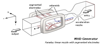
The typical solution, historically, has been to use the Hall effect to create a current that flows with the fluid. (See illustration.) This design has arrays of short, segmented electrodes on the sides of the duct. The first and last electrodes in the duct power the load. Each other electrode is shorted to an electrode on the opposite side of the duct. These shorts of the Faraday current induce a powerful magnetic field within the fluid, but in a chord of a circle at right angles to the Faraday current. This secondary, induced field makes current flow in a rainbow shape between the first and last electrodes.
Losses are less than a Faraday generator, and voltages are higher because there is less shorting of the final induced current.
However, this design has problems because the speed of the material flow requires the middle electrodes to be offset to "catch" the Faraday currents. As the load varies, the fluid flow speed varies, misaligning the Faraday current with its intended electrodes, and making the generator's efficiency very sensitive to its load.
Disc generator edit
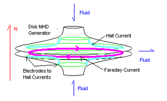
The third and, currently, the most efficient design is the Hall effect disc generator. This design currently holds the efficiency and energy density records for MHD generation. A disc generator has fluid flowing between the center of a disc, and a duct wrapped around the edge. (The ducts are not shown.) The magnetic excitation field is made by a pair of circular Helmholtz coils above and below the disk. (The coils are not shown.)
The Faraday currents flow in a perfect dead short around the periphery of the disk.
The Hall effect currents flow between ring electrodes near the center duct and ring electrodes near the periphery duct.
The wide flat gas flow reduced the distance, hence the resistance of the moving fluid. This increases efficiency.
Another significant advantage of this design is that the magnets are more efficient. First, they cause simple parallel field lines. Second, because the fluid is processed in a disk, the magnet can be closer to the fluid, and in this magnetic geometry, magnetic field strengths increase as the 7th power of distance. Finally, the generator is compact for its power, so the magnet is also smaller. The resulting magnet uses a much smaller percentage of the generated power.
Generator efficiency edit
The efficiency of the direct energy conversion in MHD power generation increases with the magnetic field strength and the plasma conductivity, which depends directly on the plasma temperature, and more precisely on the electron temperature. As very hot plasmas can only be used in pulsed MHD generators (for example using shock tubes) due to the fast thermal material erosion, it was envisaged to use nonthermal plasmas as working fluids in steady MHD generators, where only free electrons are heated a lot (10,000–20,000 kelvins) while the main gas (neutral atoms and ions) remains at a much lower temperature, typically 2500 kelvins. The goal was to preserve the materials of the generator (walls and electrodes) while improving the limited conductivity of such poor conductors to the same level as a plasma in thermodynamic equilibrium; i.e. completely heated to more than 10,000 kelvins, a temperature that no material could stand.[1][2][3][4]
But Evgeny Velikhov first discovered theoretically in 1962 and experimentally in 1963 that an ionization instability, later called the Velikhov instability or electrothermal instability, quickly arises in any MHD converter using magnetized nonthermal plasmas with hot electrons, when a critical Hall parameter is reached, hence depending on the degree of ionization and the magnetic field.[5][6][7] Such an instability greatly degrades the performance of nonequilibrium MHD generators. The prospects about this technology, which initially predicted awesome efficiencies, crippled MHD programs all over the world as no solution to mitigate the instability was found at that time.[8][9][10][11]
Consequently, without implementing solutions to master the electrothermal instability, practical MHD generators had to limit the Hall parameter or use moderately heated thermal plasmas instead of cold plasmas with hot electrons, which severely lowers efficiency.
As of 1994, the 22% efficiency record for closed-cycle disc MHD generators was held by Tokyo Technical Institute. The peak enthalpy extraction in these experiments reached 30.2%. Typical open-cycle Hall & duct coal MHD generators are lower, near 17%. These efficiencies make MHD unattractive, by itself, for utility power generation, since conventional Rankine cycle power plants easily reach 40%.
However, the exhaust of an MHD generator burning fossil fuel is almost as hot as a flame. By routing its exhaust gases into a heat exchanger for a turbine Brayton cycle or steam generator Rankine cycle, MHD can convert fossil fuels into electricity with an estimated efficiency of up to 60 percent, compared to the 40 percent of a typical coal plant.
A magnetohydrodynamic generator might also be the first stage of a gas core reactor.[12]
Material and design issues edit
MHD generators have difficult problems in regard to materials, both for the walls and the electrodes. Materials must not melt or corrode at very high temperatures. Exotic ceramics were developed for this purpose and must be selected to be compatible with the fuel and ionization seed. The exotic materials and the difficult fabrication methods contribute to the high cost of MHD generators.
Also, MHDs work better with stronger magnetic fields. The most successful magnets have been superconducting, and very close to the channel. A major difficulty was refrigerating these magnets while insulating them from the channel. The problem is worse because the magnets work better when they are closer to the channel. There are also severe risks of damage to the hot, brittle ceramics from differential thermal cracking. The magnets are usually near absolute zero, while the channel is several thousand degrees.
For MHDs, both alumina (Al2O3) and magnesium peroxide (MgO2) were reported to work for the insulating walls. Magnesium peroxide degrades near moisture. Alumina is water-resistant and can be fabricated to be quite strong, so in practice, most MHDs have used alumina for the insulating walls.
For the electrodes of clean MHDs (i.e. burning natural gas), one good material was a mix of 80% CeO2, 18% ZrO2, and 2% Ta2O5.[13]
Coal-burning MHDs have intensely corrosive environments with slag. The slag both protects and corrodes MHD materials. In particular, migration of oxygen through the slag accelerates corrosion of metallic anodes. Nonetheless, very good results have been reported with stainless steel electrodes at 900 K.[14] Another, perhaps superior option is a spinel ceramic, FeAl2O4 - Fe3O4. The spinel was reported to have electronic conductivity, absence of a resistive reaction layer but with some diffusion of iron into the alumina. The diffusion of iron could be controlled with a thin layer of very dense alumina, and water cooling in both the electrodes and alumina insulators.[15]
Attaching the high-temperature electrodes to conventional copper bus bars is also challenging. The usual methods establish a chemical passivation layer, and cool the busbar with water.[13]
Economics edit
MHD generators have not been employed for large-scale mass energy conversion because other techniques with comparable efficiency have a lower lifecycle investment cost. Advances in natural gas turbines achieved similar thermal efficiencies at lower costs, by having the turbine's exhaust drive a Rankine cycle steam plant. To get more electricity from coal, it is cheaper to simply add more low-temperature steam-generating capacity.
A coal-fueled MHD generator is a type of Brayton power cycle, similar to the power cycle of a combustion turbine. However, unlike the combustion turbine, there are no moving mechanical parts; the electrically conducting plasma provides the moving electrical conductor. The side walls and electrodes merely withstand the pressure within, while the anode and cathode conductors collect the electricity that is generated. All Brayton cycles are heat engines. Ideal Brayton cycles also have an ideal efficiency equal to ideal Carnot cycle efficiency. Thus, the potential for high energy efficiency from an MHD generator. All Brayton cycles have higher potential for efficiency the higher the firing temperature. While a combustion turbine is limited in maximum temperature by the strength of its air/water or steam-cooled rotating airfoils; there are no rotating parts in an open-cycle MHD generator. This upper bound in temperature limits the energy efficiency in combustion turbines. The upper bound on Brayton cycle temperature for an MHD generator is not limited, so inherently an MHD generator has a higher potential capability for energy efficiency.
The temperatures at which linear coal-fueled MHD generators can operate are limited by factors that include: (a) the combustion fuel, oxidizer, and oxidizer preheat temperature which limit the maximum temperature of the cycle; (b) the ability to protect the sidewalls and electrodes from melting; (c) the ability to protect the electrodes from electrochemical attack from the hot slag coating the walls combined with the high current or arcs that impinge on the electrodes as they carry off the direct current from the plasma; and (d) by the capability of the electrical insulators between each electrode. Coal-fired MHD plants with oxygen/air and high oxidant preheats would probably provide potassium-seeded plasmas of about 4200 °F, 10 atmospheres pressure, and begin expansion at Mach 1.2. These plants would recover MHD exhaust heat for oxidant preheat, and for combined cycle steam generation. With aggressive assumptions, one DOE-funded feasibility study of where the technology could go, 1000 MWe Advanced Coal-Fired MHD/Steam Binary Cycle Power Plant Conceptual Design, published in June 1989, showed that a large coal-fired MHD combined cycle plant could attain a HHV energy efficiency approaching 60 percent—well in excess of other coal-fueled technologies, so the potential for low operating costs exists.
However, no testing at those aggressive conditions or size has yet occurred, and there are no large MHD generators now under test. There is simply an inadequate reliability track record to provide confidence in a commercial coal-fuelled MHD design.
U25B MHD testing in Russia using natural gas as fuel used a superconducting magnet, and had an output of 1.4 megawatts. A coal-fired MHD generator series of tests funded by the U.S. Department of Energy (DOE) in 1992 produced MHD power from a larger superconducting magnet at the Component Development and Integration Facility (CDIF) in Butte, Montana. None of these tests were conducted for long-enough durations to verify the commercial durability of the technology. Neither of the test facilities were in large-enough scale for a commercial unit.
Superconducting magnets are used in the larger MHD generators to eliminate one of the large parasitic losses: the power needed to energize the electromagnet. Superconducting magnets, once charged, consume no power and can develop intense magnetic fields 4 teslas and higher. The only parasitic load for the magnets are to maintain refrigeration, and to make up the small losses for the non-supercritical connections.
Because of the high temperatures, the non-conducting walls of the channel must be constructed from an exceedingly heat-resistant substance such as yttrium oxide or zirconium dioxide to retard oxidation. Similarly, the electrodes must be both conductive and heat-resistant at high temperatures. The AVCO coal-fueled MHD generator at the CDIF was tested with water-cooled copper electrodes capped with platinum, tungsten, stainless steel, and electrically conducting ceramics.
Toxic byproducts edit
MHD reduces the overall production of hazardous fossil fuel wastes because it increases plant efficiency. In MHD coal plants, the patented commercial "Econoseed" process developed by the U.S. (see below) recycles potassium ionization seed from the fly ash captured by the stack-gas scrubber. However, this equipment is an additional expense. If molten metal is the armature fluid of an MHD generator, care must be taken with the coolant of the electromagnetics and channel. The alkali metals commonly used as MHD fluids react violently with water. Also, the chemical byproducts of heated, electrified alkali metals and channel ceramics may be poisonous and environmentally persistent.
History edit
The first practical MHD power research was funded in 1938 in the U.S. by Westinghouse in its Pittsburgh, Pennsylvania laboratories, headed by Hungarian Bela Karlovitz. The initial patent on MHD is by B. Karlovitz, U.S. Patent No. 2,210,918, "Process for the Conversion of Energy", August 13, 1940.
World War II interrupted development. In 1962, the First International Conference on MHD Power was held in Newcastle upon Tyne, UK by Dr. Brian C. Lindley of the International Research and Development Company Ltd. The group set up a steering committee to set up further conferences and disseminate ideas. In 1964, the group set up a second conference in Paris, France, in consultation with the European Nuclear Energy Agency.
Since membership in the ENEA was limited, the group persuaded the International Atomic Energy Agency to sponsor a third conference, in Salzburg, Austria, July 1966. Negotiations at this meeting converted the steering committee into a periodic reporting group, the ILG-MHD (international liaison group, MHD), under the ENEA, and later in 1967, also under the International Atomic Energy Agency. Further research in the 1960s by R. Rosa established the practicality of MHD for fossil-fueled systems.
In the 1960s, AVCO Everett Aeronautical Research began a series of experiments, ending with the Mk. V generator of 1965. This generated 35 MW, but used about 8 MW to drive its magnet. In 1966, the ILG-MHD had its first formal meeting in Paris, France. It began issuing a periodic status report in 1967. This pattern persisted, in this institutional form, up until 1976. Toward the end of the 1960s, interest in MHD declined because nuclear power was becoming more widely available.
In the late 1970s, as interest in nuclear power declined, interest in MHD increased. In 1975, UNESCO became persuaded the MHD might be the most efficient way to utilise world coal reserves, and in 1976, sponsored the ILG-MHD. In 1976, it became clear that no nuclear reactor in the next 25 years would use MHD, so the International Atomic Energy Agency and ENEA (both nuclear agencies) withdrew support from the ILG-MHD, leaving UNESCO as the primary sponsor of the ILG-MHD.
Former Yugoslavia development edit
Over more than a ten-year span, engineers in former Yugoslavian Institute of Thermal and Nuclear Technology (ITEN), Energoinvest Co., Sarajevo, had built the first experimental Magneto-Hydrodynamic facility power generator in 1989. It was here it was first patented.[16][17]
U.S. development edit
In the 1980s, the U.S. Department of Energy began a vigorous multiyear program, culminating in a 1992 50 MW demonstration coal combustor at the Component Development and Integration Facility (CDIF) in Butte, Montana. This program also had significant work at the Coal-Fired-In-Flow-Facility (CFIFF) at University of Tennessee Space Institute.
This program combined four parts:
- An integrated MHD topping cycle, with channel, electrodes, and current control units developed by AVCO, later known as Textron Defence of Boston. This system was a Hall effect duct generator heated by pulverized coal, with a potassium ionisation seed. AVCO had developed the famous Mk. V generator, and had significant experience.
- An integrated bottoming cycle, developed at the CDIF.
- A facility to regenerate the ionization seed was developed by TRW. Potassium carbonate is separated from the sulphate in the fly ash from the scrubbers. The carbonate is removed, to regain the potassium.
- A method to integrate MHD into preexisting coal plants. The Department of Energy commissioned two studies. Westinghouse Electric performed a study based on the Scholtz Plant of Gulf Power in Sneads, Florida. The MHD Development Corporation also produced a study based on the J.E. Corrette Plant of the Montana Power Company of Billings, Montana.
Initial prototypes at the CDIF were operated for short durations, with various coals: Montana Rosebud, and a high-sulphur corrosive coal, Illinois No. 6. A great deal of engineering, chemistry, and material science was completed. After the final components were developed, operational testing completed with 4,000 hours of continuous operation, 2,000 on Montana Rosebud, 2,000 on Illinois No. 6. The testing ended in 1993. [citation needed]
Japanese development edit
The Japanese program in the late 1980s concentrated on closed-cycle MHD. The belief was that it would have higher efficiencies, and smaller equipment, especially in the clean, small, economical plant capacities near 100 megawatts (electrical) which are suited to Japanese conditions. Open-cycle coal-powered plants are generally thought to become economical above 200 megawatts.
The first major series of experiments was FUJI-1, a blow-down system powered from a shock tube at the Tokyo Institute of Technology. These experiments extracted up to 30.2% of enthalpy, and achieved power densities near 100 megawatts per cubic meter. This facility was funded by Tokyo Electric Power, other Japanese utilities, and the Department of Education. Some authorities believe this system was a disc generator with a helium and argon carrier gas and potassium ionization seed.
In 1994, there were detailed plans for FUJI-2, a 5 MWe continuous closed-cycle facility, powered by natural gas, to be built using the experience of FUJI-1. The basic MHD design was to be a system with inert gases using a disk generator. The aim was an enthalpy extraction of 30% and an MHD thermal efficiency of 60%. FUJI-2 was to be followed by a retrofit to a 300 MWe natural gas plant.
Australian development edit
In 1986, Professor Hugo Karl Messerle at The University of Sydney researched coal-fueled MHD. This resulted in a 28 MWe topping facility that was operated outside Sydney. Messerle also wrote one of the most recent reference works (see below), as part of a UNESCO education program.
A detailed obituary for Hugo is located on the Australian Academy of Technological Sciences and Engineering (ATSE) website.[18]
Italian development edit
The Italian program began in 1989 with a budget of about 20 million $US, and had three main development areas:
- MHD Modelling.
- Superconducting magnet development. The goal in 1994 was a prototype 2 m long, storing 66 MJ, for an MHD demonstration 8 m long. The field was to be 5 teslas, with a taper of 0.15 T/m. The geometry was to resemble a saddle shape, with cylindrical and rectangular windings of niobium-titanium copper.
- Retrofits to natural gas powerplants. One was to be at the Enichem-Anic factor in Ravenna. In this plant, the combustion gases from the MHD would pass to the boiler. The other was a 230 MW (thermal) installation for a power station in Brindisi, that would pass steam to the main power plant.
Chinese development edit
A joint U.S.-China national programme ended in 1992 by retrofitting the coal-fired No. 3 plant in Asbach.[citation needed] A further eleven-year program was approved in March 1994. This established centres of research in:
- The Institute of Electrical Engineering in the Chinese Academy of Sciences, Beijing, concerned with MHD generator design.
- The Shanghai Power Research Institute, concerned with overall system and superconducting magnet research.
- The Thermoenergy Research Engineering Institute at the Nanjing's Southeast University, concerned with later developments.
The 1994 study proposed a 10 W (electrical, 108 MW thermal) generator with the MHD and bottoming cycle plants connected by steam piping, so either could operate independently.
Russian developments edit

In 1971, the natural-gas-fired U-25 plant was completed near Moscow, with a designed capacity of 25 megawatts. By 1974 it delivered 6 megawatts of power.[19] By 1994, Russia had developed and operated the coal-operated facility U-25, at the High-Temperature Institute of the Russian Academy of Science in Moscow. U-25's bottoming plant was actually operated under contract with the Moscow utility, and fed power into Moscow's grid. There was substantial interest in Russia in developing a coal-powered disc generator. In 1986 the first industrial power plant with MHD generator was built, but in 1989 the project was cancelled before MHD launch and this power plant later joined to Ryazan Power Station as a 7th unit with ordinary construction.
See also edit
References edit
- ^ Kerrebrock, Jack L.; Hoffman, Myron A. (June 1964). "Non-Equilibrium Ionization Due to Electron Heating. Theory and Experiments" (PDF). AIAA Journal. 2 (6): 1072–1087. Bibcode:1964AIAAJ...2.1080H. doi:10.2514/3.2497.
- ^ Sherman, A. (September 1966). "MHD Channel Flow with Non-Equilibrium lonization" (PDF). The Physics of Fluids. 9 (9): 1782–1787. Bibcode:1966PhFl....9.1782S. doi:10.1063/1.1761933.
- ^ Argyropoulos, G. S.; Demetriades, S. T.; Kentig, A. P. (1967). "Current Distribution in Non-Equilibrium J×B Devices" (PDF). Journal of Applied Physics. 38 (13): 5233–5239. Bibcode:1967JAP....38.5233A. doi:10.1063/1.1709306.
- ^ Zauderer, B.; Tate, E. (September 1968). "Electrical characteristics of a linear, nonequilibrium, MHD generator" (PDF). AIAA Journal. 6 (9): 1683–1694. Bibcode:1968AIAAJ...6.1685T. doi:10.2514/3.4846.
- ^ Velikhov, E. P. (1962). Hall instability of current carrying slightly ionized plasmas. 1st International Conference on MHD Electrical Power Generation. Newcastle upon Tyne, England. p. 135. Paper 47.
- ^ Velikhov, E. P.; Dykhne, A. M. "Plasma turbulence due to the ionization instability in a strong magnetic field". In P. Hubert; E. Crémieu-Alcan (eds.). Volume IV. Proceedings of the conference held July 8-13, 1963. 6th International Conference on Phenomena in Ionized Gases. Paris, France. p. 511. Bibcode:1963pig4.conf..511V.
- ^ Velikhov, E. P.; Dykhne, A. M.; Shipuk, I. Ya (1965). Ionization instability of a plasma with hot electrons (PDF). 7th International Conference on Ionization Phenomena in Gases. Belgrade, Yugoslavia.
- ^ Shapiro, G. I.; Nelson, A. H. (12 April 1978). "Stabilization of ionization instability in a variable electric field". Pis'ma V Zhurnal Tekhnischeskoi Fiziki. 4 (12): 393–396. Bibcode:1978PZhTF...4..393S.
- ^ Murakami, T.; Okuno, Y.; Yamasaki, H. (December 2005). "Suppression of ionization instability in a magnetohydrodynamic plasma by coupling with a radio-frequency electromagnetic field" (PDF). Applied Physics Letters. 86 (19): 191502–191502.3. Bibcode:2005ApPhL..86s1502M. doi:10.1063/1.1926410.
- ^ Petit, J.-P.; Geffray, J. (June 2009). "Non equilibrium plasma instabilities". Acta Physica Polonica A. 115 (6): 1170–1173. Bibcode:2009AcPPA.115.1170P. CiteSeerX 10.1.1.621.8509. doi:10.12693/aphyspola.115.1170.
- ^ Petit, J.-P.; Doré, J.-C. (2013). "Velikhov electrothermal instability cancellation by a modification of electrical conductivity value in a streamer by magnetic confinement". Acta Polytechnica. 53 (2): 219–222. doi:10.14311/1765. hdl:10467/67041.
- ^ Smith BM, Anghaie S, Knight TW (2002). Gas Core Reactor-MHD Power System with Cascading Power Cycle. ICAPP'02: 2002 International congress on advances in nuclear power plants, Hollywood, FL (United States), 9-13 Jun 2002. OSTI 21167909. OSTI: 21167909.
- ^ a b Rohatgi, V. K. (February 1984). "High temperature materials for magnetohydrodynamic channels". Bulletin of Materials Science. 6 (1): 71–82. doi:10.1007/BF02744172. Retrieved 19 October 2019.
- ^ Bogdancks M, Brzozowski WS, Charuba J, Dabraeski M, Plata M, Zielinski M (1975). "MHD Electrical Power Generation". Proceedings of 6th Conference, Washington DC. 2: 9.
- ^ Mason TO, Petuskey WT, Liang WW, Halloran JW, Yen F, Pollak TM, Elliott JF, Bowen HK (1975). "MHD Electrical Power Generation". Proceedings of 6th Conference, Washington DC. 2: 77.
- ^ Bajović, Valentina S. (1994). "The correct quasi-one-dimensional model of the fluid flow in a Faraday segmented MHD generator channel". Energy Conversion and Management. 35 (4): 281–291. doi:10.1016/0196-8904(94)90061-2.
- ^ Bajović, Valentina S. (1996). "A reliable tool for the design of shape and size of Faraday segmented MHD generator channel". Energy Conversion and Management. 37 (12): 1753–1764. doi:10.1016/0196-8904(96)00036-2.
- ^ "MESSERLE, Hugo Karl". Australian Academy of Technological Sciences and Engineering (ATSE). Archived from the original on 2008-07-23..
- ^ Donald G. ink, H. Wayne Beatty (ed), Standard Handbook for Electrical Engineers, 11th Edition, Mc Graw Hill, 1978 ISBN 0-07-020974-X page 11–52
Further reading edit
- Sutton, George W.; Sherman, Arthur (July 2006). Engineering Magnetohydrodynamics. Dover Civil and Mechanical Engineering. Dover Publications. ISBN 978-0486450322.
- Hugo K. Messerle, Magnetohydrodynamic Power Generation, 1994, John Wiley, Chichester, Part of the UNESCO Energy Engineering Series (This is the source of the historical and generator design information).
- Shioda, S. "Results of Feasibility Studies on Closed-Cycle MHD Power Plants", Proc. Plasma Tech. Conf., 1991, Sydney, Australia, pp. 189–200.
- R.J. Rosa, Magnetohydrodynamic Energy Conversion, 1987, Hemisphere Publishing, Washington, D.C.
- G.J. Womac, MHD Power Generation, 1969, Chapman and Hall, London.
External links edit
- MHD generator Research at the University of Tennessee Space Institute (archive) - 2004
- Model of an MHD-generator at the Institute of Computational Modelling, Akademgorodok, Russia - 2003
- The Magnetohydrodynamic Engineering Laboratory Of The University Of Bologna, Italy - 2003
- High Efficiency Magnetohydrodynamic Power Generation - 2015